 |
RC640 radio unit |
What's this?
This is a page about the RC640 transceiver, and about my exploits with it.
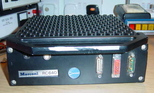
The RC640 "Repeater Mobile" is a boot-mount transceiver with a separate control head unit. It was made in the 1980's by Marconi, Chelmsford and sold to the Metropolitain Police (London police). It appears they were also used by ambulances in the West Midlands and railways in Iraq. "Repeater Mobile" comes from its ability to act as a repeater for the Police handhelds when the officers leave the vehicle. It is also classed a "Wideband" mobile due to the wide tuning band without factory realignment. RC640 is capable of full-duplex operation with two antennas but may also be fitted simplex with one.
I'm told only about 100 were made, and many more RC690 (AM unit) were made.
Inside RC640
This RC640 was given to me by a local radio amateur.
The radio unit appears to be a trials or evaluation unit. Reasons for believing this are: serial number is engraved 001; production serials never start at 1. Development units rarely get engraved serial numbers. The main chassis seems to be machined out of solid; the lid, base, front and all parts of the head unit are castings. Production models would not be machined from solid but it may be done to make prototypes. Prototypes are often not painted at all. The processor board has poor tinning and hand-soldering typical of a prototype board assembled in development. The unit it too clean to have spent life in a service vehicle.
On the other hand, the radio has production test stamps. This gives me some confidence it was fully working at some time in the past, although maybe not with the set of parts it now has! Most of the boards have been flow-soldered - the processor board may have been substituted from some earlier unit after it died.
I have suspicion that the control head is an early production unit that has never been tested. "early" because it has keypad labels that were later blanked out, and "untested" as it has no test stamps, no EPROM, and a resistor was missing that I've found to be necessary. The unit was probably mothballed as there were more heads than working radios. The IDC connectors are too wide - someone "made do"; This is typical of development but doesn't happen in production. The condition of the unit looks like it's never been used.
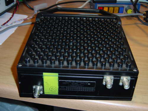 |
RC640 radio unit - rear view
Shows test stamps, The identity plate with engraved serial number is hardly visible in this shot. The BNC on the left is the Rx antenna. The middle BNC is the Tx antenna. The right BNC is the Rx port of the Tx/Rx switch. For simplex, link the right and left BNCs with a short patch lead and connect the antenna to the middle BNC. |
RC640 is a duplex radio; it has separate Tx and Rx synthesisers and antenna connectors.
RC640 can also work in simplex mode; it simply mutes Rx audio in Tx! There is an antenna switch relay provided for simplex single-antenna use.
RC640 can also operate as a repeater, with various tone-access schemes including selcall and CTCSS. In this mode of operation it scans two channels for activity and will activate repeater operation in the appropriate direction.
| Channels | 99 | nb. Met police firmware restricts to 20 - fixed |
| Frequency range | 143 � 156MHz | |
| Channel spacing | 12.5kHz | |
| Modulation | FM +-3.5kHz deviation | Measured |
| Tx Power | 26W | Measured |
| Rx sensitivity | -120dBm for 10dB SINAD @ 1kHz dev | Measured |
| IF bandwidth | +-3.5kHz | Measured |
| Power | 12V +ve or -ve earth 1.1A Rx, 7.0A Tx | Measured |
The radio supports CTCSS transmit and receive tone-squelch; set by dip-switches inside the radio and head unit.
The radio supports detection and generation of 5-tone EEA-standard selcall tones. In fact the head-unit's tone generator can send almost any in-band tone (eg. 1750 Hz). The Met Police firmware only uses selcall for validating access to the repeater function.
The radio has a time-out timer which bleeps you shortly before expiry and then cuts off the Tx.
The radio is linked to the control head via a 15-way female-female D-type cable with all pins wired one-to-one.
The 15-way male "facilities" connectors on both the radio and control head must be fitted with link plugs to bridge the audio and PTT through.
A handset of some kind connects to the head unit with a 5-pin DIN plug; presumably telephone-type with a pressel suitable for duplex working.
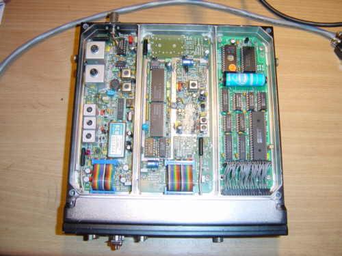 |
RC640 bottom view
Rx RF, IF & demod is on the left. Rx synthesiser in the centre; screen covers removed. Processor board on the right. The lithium cell is still good; over 3V. |
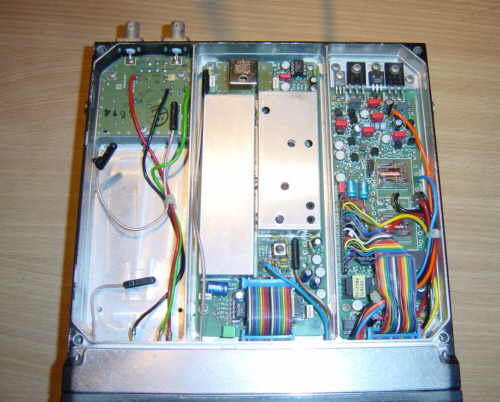 |
RC640 top view
The PSU & audio is on the right. Tx synthesiser in the centre. At the rear left is the antenna switch. The gap on the left takes the PA which is on the lid (not shown). |
Tx Synth - Deviation
Tx synth RV1 - AF deviation -
ancilliaries (xfmr bal input pins 1&2)
Tx synth RV2 - AF deviation
- control head (mic, CTC, EEA tones)
Tx synth RV3 - AF deviation -
radio CTCSS (FX335)
Tx synth RV4 affects Tx linearity - my advice:
don't twiddle.
Varicap voltage tuning is used in the Tx & Rx synth LO filters and Rx front end RF filters. No re-adjustment is needed for 2m band - unless you messed with them! It is designed like this to support a wide Tx/Rx split for duplex/repeater working and to work with Tx & Rx either way round. If you tweak, be aware the filter centre-frequency will shift with radio tune frequency; ie. set radio for 145MHz and set filters on 145MHz. Don't even look at them if the synths are off-frequency. Varicap tuning voltages are derived from the synth loops.
Receiver - Squelch level
Receiver RV1 - squelch detect
A
Receiver RV2 - signal level detect A
Receiver RV3 - squelch detect
B
Receiver RV4 - signal level detect B
To adjust squelch, adjust
RV3. The firmware ignores the rest.
PSU regulator
PSU RV1 - VS1 supply volts (Tx key gated
rail)
PSU RV2 - +10VB supply current limit
PSU RV3 - +10VB supply
voltage
PSU RV4 - +10VA supply current limit
PSU RV5 - +10VA supply
voltage
PSU RV6 - Facilities Xfmr Balanced audio out level
VS1
supply is power to 1st stage of the PA module
RV6 was fully CW.
At present I can't say how the PSU should be set up, don't fiddle. When I say "current limit", it's a protection of the LDO regulators that acts to prevent overdriving the pass transistors if the supply is overloaded or the input voltage is too low.
CTCSS switches
| Tone (Hz) |
RMC letter |
D0...D5 | Radio Unit | Control Head | ||||||||||
| S1 | S2 | S3 | S4 | S5 | S6 | S1 | S2 | S3 | S4 | S5 | S6 | |||
| 67.0 | A | 111111 | 1 | 1 | 1 | 1 | 1 | 1 | 1 | 1 | 1 | 1 | 1 | 1 |
| 71.9 | B | 111110 | 0 | 1 | 1 | 1 | 1 | 1 | 1 | 1 | 1 | 1 | 1 | 0 |
| 77.0 | C | 111100 | 0 | 0 | 1 | 1 | 1 | 1 | 1 | 1 | 1 | 1 | 0 | 0 |
| 82.5 | D | 011110 | 0 | 1 | 1 | 1 | 1 | 0 | 1 | 1 | 1 | 0 | 1 | 0 |
| 88.5 | E | 011100 | 0 | 0 | 1 | 1 | 1 | 0 | 1 | 1 | 1 | 0 | 0 | 0 |
| 94.8 | F | 101110 | 0 | 1 | 1 | 1 | 0 | 1 | 1 | 1 | 0 | 1 | 1 | 0 |
| 103.5 | G | 001110 | 0 | 1 | 1 | 1 | 0 | 0 | 1 | 1 | 0 | 0 | 1 | 0 |
| 110.9 | H | 110110 | 0 | 1 | 1 | 0 | 1 | 1 | 1 | 0 | 1 | 1 | 1 | 0 |
| 118.8 | J | 010110 | 0 | 1 | 1 | 0 | 1 | 0 | 1 | 0 | 1 | 0 | 1 | 0 |
Radio PSU board: S8 is by pin 12 of FX335J. "1" (open) is toward FX335J.
Radio S7 can be used to make Rx audio bypass FX335 completely. Leave open.
(We are assuming here that DIP switches in all RC640's are fitted the same way round as mine.)
Filling
The channels are stored in the radio in battery-backed RAM.
Each channel can specify Tx & Rx synth setup, time out timer, CTCSS modes, and duplex mode. There is also some non-channel data including selcall identity and scanning dwell times.
The RC640 is intended to be loaded from a fill-gun unit connected in place of the control head. At the moment I don't know what the gun looks like, although it has 7-segment displays, and a number of buttons with associated LEDs. The gun could carry a number of fills, and the buttons select which one to load to the radio. The gun, in turn, received its fill from a deivce called a "Sierra" about which I know nothing at all.
The gun essentially transfers records of intelhex using a serial handshaking protocol. Fills have versions and editions and radio types, and so the appropriate fill selection becomes automatic when simply updating a radio. Fills also have a "status block" which contains a checksum and version info; checksum is only ever checked after filling and never at powerup. Selcalls are in the fill and are unique to radios so it's not clear how each fill was customised. Because it's intelhex, a fill can choose not to overwrite the selcall, but then what happens to the checksum?
It is possible that it could be carried out from any PC terminal program simply by typing "G" and sending an intelhex file. The intelhex file can be generated from a freeware macro assembler (like asl) and a few macros.
I have already built a new radio firmware EPROM that loads a default fill on powerup if none is detected, and I write the table that determines what that fill is.
The serial interface between the radio and control head is RS422; 2400 baud, 1 start, 7 data, odd parity, 1 stop. At powerup, the radio sends the letter "C" at intervals and awaits an "H" reply from a control head or a "G" from a fill gun.
Operation
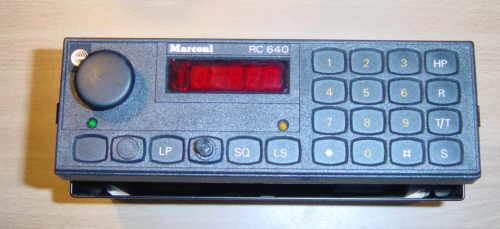 |
RC640 control head front view.
There is a slide-in mounting bracket, but there are also has spring clips to retain the head unit in a square dashboard opening. The main unit also takes a bracket but I haven't got one. |
Big knob - push/pull the knob in to switch off/on. Turn to set volume. If it won't click when you push/pull then tighten the allen grubscrew!
The decimal point in the display shows it's on. If it's dim that's normal; if it comes on bright it's an indication the CPU is not running and is not scanning the display & polling the keypad.
Channels are entered by pressing two digits and a "*". "00" is illegal.
# key (cancel) - cancels an unfinished entry or cancels repeater mode.
HP key - (REPh) - repeater mode
R key - (REPnn) - repeater mode. Follow by 2 digit channel and "*".
The difference in REP and REPh is the channels used. My theory is that one offers a local repeat between handhelds and the other between handhelds and HQ.
T/T key - talkthrough key. The key is blank on some units. Key no longer has a function.
S key - shows the 5-digit selcall number. At one time it was also possible to edit the selcall.
The blank key and green LED on the LHS is the "PA" key. On the RC690 this enables Public Address mode. The PA output isn't present on the RC640.
LP (lamps) key - originally turned on the keypad illumination. The function has been disabled and the lamps are lit permanently. The key is blank on later units.
Between LP and SQ is a small knob that dims the display and illumination.
SQ (squelch) - pressing this holds open the squelch mute. At one time this was a toggled function. If I get my way it will be again.
LS (loudspeaker) button - enables the loudspeaker, indicated by the amber LED. In certain modes, speaker will be disabled, eg. Tx Duplex.
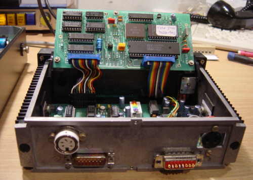 |
RC640 control head - rear view with board open
Note link plug in facilities connector. |
| RC640 Power connector pinout - D shell with 5 pins + 2 power inserts - chassis male | |
| pin 1 | tbd |
| pin 2 | tbd |
| pin 3 | tbd |
| pin 4 | tbd |
| pin 5 | tbd |
| insert A1 | supply 0V |
| insert A2 | supply +12V |
The radio chassis is DC isolated from supply 0V although chassis is RF ground.
| RC640 Handset connector pinout - 5-pin DIN 240 degree chassis female | |
| pin 1 | - ear |
| pin 2 | - +5V |
| pin 3 | - PTT |
| pin 4 | - mic |
| pin 5 | - 0V |
The magnetic mic is connected between 4 & 5.
The earpiece is connected between 1 & 5.
The PTT switch is connected between 2 & 3 (yes, to +5V)
For duplex, some kind of handset or headset is required. I recommend separate ground wires for mic and ear back to the connector to avoid crosstalk. Fist speaker-microphones could be used for simplex if they have separate mic and speaker or if the PTT switch will swop the connections. Note that fist mics usually have PTT-to-ground; to rewire it you need at least 5 wires in the cable.
One warning: Don't short the PTT to +12V as it connects directly to the processor, which will probably die instantly. In fact ESD protection is lacking on many signals. The PTT pin is next to the +12V pin on the facilities connector.
| RC640 Facilities connector pinout - 15-way D-type - chassis male | ||
| pin 1 | - Tx audio xfmr balanced input | |
| pin 2 | - Tx audio xfmr balanced input | |
| pin 3 | - 0V | |
| pin 4 | - PTT in | 1=Tx (HCMOS 5V signal) |
| pin 5 | - Tx audio in | |
| pin 6 | - 0V | |
| pin 7 | - Rx audio in | |
| pin 8 | - Mute out | 1=muted (HCMOS 5V signal) |
| pin 9 | - Rx audio xfmr balanced out | |
| pin 10 | - Rx audio xfmr balanced out | |
| pin 11 | - +12V | |
| pin 12 | - PTT out | 1=Tx (HCMOS 5V signal) |
| pin 13 | - Tx audio out | |
| pin 14 | - 0V | |
| pin 15 | - Rx audio out | |
For normal operation, a facilities bypass plug must be fitted at both radio and control head with the following pins linked:
| pin4 - pin12 | pin5 - pin13 | pin7 - pin14 |
| RC640 Inter-unit cable pinout - 15-way D-type - chassis male | |
| pin 1 | - on/off switch A |
| pin 2 | - on/off switch B |
| pin 3 | - Rx AF from radio |
| pin 4 | - +12V |
| pin 5 | - bal AF ancilliaries Tx in |
| pin 6 | - bal AF ancilliaries Tx in |
| pin 7 | - TxD+ |
| pin 8 | - RxD- |
| pin 9 | - 0V |
| pin 10 | - 0V |
| pin 11 | - Tx AF to radio |
| pin 12 | - bal AF ancilliaries Rx out |
| pin 13 | - bal AF ancilliaries Rx out |
| pin 14 | - TxD- |
| pin 15 | - RxD+ |
Firmware
The firmware must be programmed in a 2732 EPROM. 450ns chips work for me.
The radio and head unit use Z8681 (Zilog Z8 family) microcontrollers. "asl" is the only freeware macro assembler I could find that supports Z8. http://john.ccac.rwth-aachen.de:8000/as/It runs on Unix (or anything posix), MS-DOS and MS-Windows (via cygwin). A free Z8 assembler can also be downloaded from Zilog.
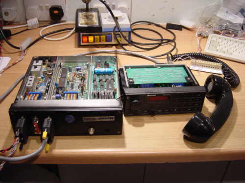 |
Development system setup
A short interconnect cable has been made as a thick 5m one takes over the floor. The telephone-type handset is ex-marconi with a matching plug but the plug has been re-wired to agree with the radio pinout. A 15-way D-type breakout sniffs the serial data between the radio and head processors and feeds it to a DOS PC running PALS Datascope. The lid and PA module have been disconnected. |
Latest News
The latest hex files and source files have been found. We were fortunate to trace the identity of the software from the number on the head unit CPU board! A new EPROM for the head unit programmed. The sources have been ported to the ASL macro-assembler and rebuilt. A corruption was found in the source which has been fixed so it produces identical ROM images to the originals.
The radio firmware has had a table added and code which loads it to the channel RAM if the RAM is found not to contain a signature byte. Some channels have been created, but the synth data is dummy.
The limit of 20 channels has been upped to 99.
After lots of reverse-engineering work I determined a resistor was missing from the control panel (a pulldown for the PTT line). Without it an input to the CPU was floating and generated an overwhelming number of events to be processed. This would even cause the LED displays to blank intermittently as the display multiplex stops getting serviced.
Having fixed this, the control head CPU looks sane and with a correctly wired handset we get mic audio down the cable to the radio unit when we press PTT. We move on to the radio unit.
The radio unit CPU wasn't running. CPU seemed too warm for comfort and was not sending any serial data. Some bus waveforms looked bad and they changed when pressing on the board. A pin on the address latch was bent under the chip, not inserted in the chip socket. (GND pin I think). The CPU also appears faulty. Confirmed by swapping the CPU from the head. The Z8681 is obsolete.
Thanks to Jan Verhoeven http://www.fruttenboel.tomaatnet.nl/ who posted me a Z8681 chip from the Netherlands! The control head and radio unit now talk to each other, and I can select channels 1 to 99. I get the display "-FAIL" which indicates synth out-of-lock. (The channel data isn't correct.) The SQ key causes a blast of receiver noise to come from the handset. Handset PTT causes relay clicky noises from the radio. "S" displays the selcall ID as "12345", that I set. Good progress!
The control head firmware has been modified to return the squelch key to toggle behaviour.
It appears that I now have no impediment to modifying the sources, burning new EPROMs and getting them to work fine. Now I know enough about Z8 assembly to write code that doesn't crash! Even better, all my new code has worked first-time.
I'd like to do mods to remove the need to type * when entering channels. Another useful addition would be the capability to enable a 1750Hz repeater access beep on desired channels. And perhaps also the entry and display of frequencies in the channel store.
19-12-2003
Channel table has been updated several times now, and I finally know how to set up the synthesisers. I have a complicated new macro which does all the number work given two frequencies. I've now got a table with a useful set of 2m-band frequencies.
Tests show that the synths are producing the desired frequencies. Frequency counter shows 780Hz high in 145MHz; could tweak the radio but really should check the counter accuracy first.
Connected a whip antenna on a magbase and heard the first 2m amateur station on 145.725MHz using an RC640; repeater GB3DA transmitting station ID. Time to upload some EPROM images to the web?
29-12-2003
Performance measurements have been done with RF test gear, adjustments checked and frequency reference and deviation set. The system can now be used on-air. Deviation of CTCSS could not be set (see below).
During testing, some bugs have been found:
After changing channel, the AF goes mute at the radio end and gets out-of-sync with the control head's SQ state. It needs 2 presses of SQ to open it. It seems not to happen selecting ch 1 & 2, but does on all the others I tried.
Channels 51-99 cause "-FAIL" rather than rejecting the channel change. Looks like I need to zero the RAM for unspecified channels.
The radio doesn't seem to have any normal squelch. This is a royal pain - must look into this.
2-1-2004
The Rx board provides 4 indicators of signal to the CPU - 2nd IF signal level and "squelch noise" with 2 thresholds each. Only one is used by software. Examining the code in detail leads me to suspect a software bug.
Squelch muting is implemented at the head end, so messages are sent to indicate mute state. Facilities audio is gated by Rx of CTCSS (if enabled) but not muted by squelch. A hardware mute signal reflecting squelch mute is fed to the connector for use as a "signal present" indicator by external units.
The settings for the radio CTCSS de/encoder seems not to have had an effect. No CTCSS is generated for chans 1-3 where we had it enabled (or so we thought).
Need to do more RF tests to verify that the squelch detectors are working.
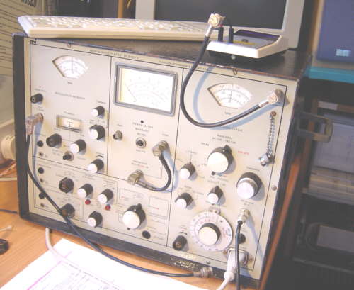 |
Mobile Radio Testset
Early Marconi Instruments vintage, kindly loaned by Chelmsford Amateur Radio Society. On the top is my Thandar (aka Sinclair) 200MHz frequency counter. |
8-1-2004
RF tests done with aid of an MI mobile-radio test set borrowed from Chelmsford Radio Amateur Society. Squelch appears to be working on chans 1 and 2 where we set "Tx CTCSS" but not on chan 45 where we didn't. We did lots of logging of IO pin states and serial messages with various channels, modes and signal levels input to the receiver.
2 more bugs detected in the original RC640 software:
The mute output to facilities on the radio is not affected by the SQ key whereas the one on the control head is. The facilities ports are supposed to be the same. (In the head unit the mute line to facilities actually does control the AF mute gate so it must show unmute when you open SQ. We could make the radio copy the head unit, for what it's worth.)
In duplex with Tx keyed, the SQ key has no effect. OK, so SQ is ignored in Tx in any mode, but in duplex the receiver is active. Would anyone muck with the squelch while yakking away in duplex? Possibly. But a brief drop of the PTT to press SQ won't kill anyone.
10-1-2004
Squelch/CTCSS problems were caused by me not fully understanding the function of the channel mode byte flags. Now I do.
Firmware has been revised and new EPROMS produced. Tests positive.
Squelch enabled and working on all channels.
CTCSS generator working on channels 1-3 intended for repeater
access.
nb. it is the Radio unit generator in use. Set this DIP switch.
CTCSS decode mute not enabled on any channel (but we know how to do it).
SQ key state doesn't get out-of-sync with radio when channel changed.
Control head keypad editing of selcall ID has been re-enabled. Doubt anyone has a use, but I'd like to see how it works anyhow. I don't see as it gets saved back to radio SRAM so changes are volatile.
I suppose the next move is using on-air. Repeater mode is yet to be explored. And perhaps improving the choices of channels in the store.
After a substantial lapse, the obtaining of a number of RC690 sets and various enquiries prompted an RC640 experiments resurgence!
We have a new channel table from G4FPH with all the repeater frequencies, simplex channels and reverse repeater frequencies. We've also played with the RC690 head unit connected to the RC640 radio, and yes that works! This version is also now technically capable of 255 channels, although there are presently only test frequencies above 100.
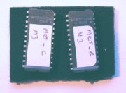 |
EPROMS! Build 10 firmware set, Intelhex files, burn to two 2732 EPROMs. MET_R.HEX radio unit EPROM MET_C.HEX control head EPROM CHAN.ASM channel table source information |
EPROMS build 10 in zip format to download Build10.zip
Interfacing for packet
Some thoughts, not yet proven:
The PTT input must be driven high to 5V to transmit. Somewhat different to most radios. This is true at the handset or facilities. Facilities has a 12V supply but no 5V. A 5V supply needs to be derived to operate PTT, or PTT clamped with diodes and fed with a resistor. If you want to merge PTT sources, some gating is needed, or a diode-OR arrangement. Take care not to drive the PTT output, at the head unit it's the handset PTT to +5V, at the radio it's a logic output.
The facilities 12V could be used to power TNCs directly.
Use of handset does not mute a modem at the facilities, although circuits at the facilities port could be made to do this (detect PTT out and mute modem). Mic audio can be suppressed when feeding in modem audio via facilities by breaking the facilities Tx audio link.
The facilities port has very useful transformer-balanced audio in and out. The annoyance here is that Rx audio is not squelch-gated. None or the Rx audio on facilities is squelch-gated, it's there blasting noise when the mute silences the handset and speaker. It's gated by CTCSS decode, if you want, but that's no help. Baycom and other types of modems like to have gated audio, otherwise the PC or processor gets fed reams of garbage to decode. The "mute" output on facilities can be used to drive an external gate, or drive DCD to the PC.
Hmm, it's possible that the CTCSS decoder could be put into a state where it effectively kills the Rx audio. Firmware could do this in response to the RF mute detect input, thereby producing the desired squelched audio at facilities. We could use spare mode flags to enable this effect on packet channels.